Variable speed three-phase induction generator with wound rotor
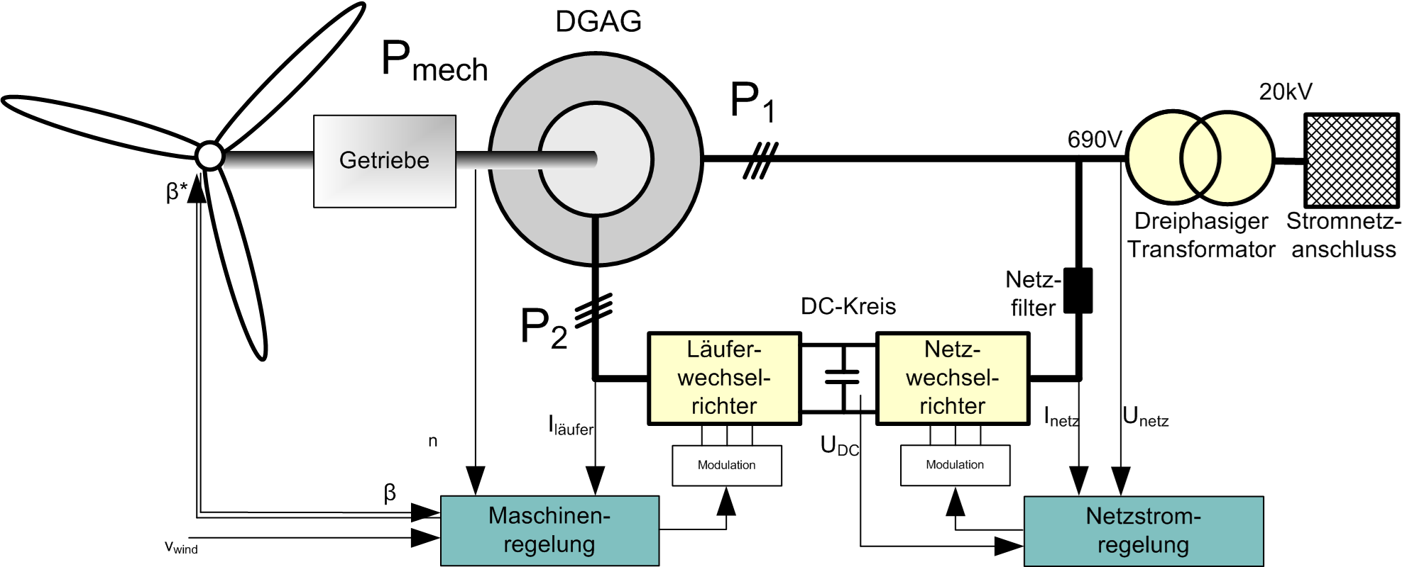
This experiment deals with a variable speed three-phase induction generator whose rotor winding is fed by a converter via slip rings. Depending on the converter design, the induction machine can efficiently be operated within a relatively vast speed range by feeding amplitude- and frequency-variant currents into the rotor circuit.
Using a DC machine as load, different characteristics are determined for engine braking as well as for regenerative braking, and the influence of the converter control on the motor performance is investigated.
The items analyzed and visualized in this experiment are e.g.
- operation as cage rotor for comparison,
- power flow on rotor and stator side at variable speed and converter supply,
- influence of rotor voltages and currents and their frequency on the power flow.
Three-phase cage induction motor fed by pulse-controlled converter
This experiment deals with a variable speed cage induction motor fed by a pulse-controlled converter, as it is commony used in industry. Different modes of voltage-frequency control can be selected on the power converter. By this means, typical motor characteristics can be invesigated, e.g.
- voltage-frequency characteristics (linear and quadratic function),
- the respective speed-torque characteristics,
- slip compensation.
Electronically commutated motors
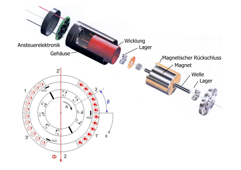
This experiment focuses on the operation of an EC motor. EC motors are electronically commutated DC motors. The rotor position is determined by a rotor position sensor which is then evaluated by a control electronics. The armature windings are switched on and off via power semiconductors in the control electronics at predefined instants of time.
The experiment is made on a controlled as well as on a non-controlled circuit. For this purpose, a control logic must be developed first. In addition, the variations in time of the motor current are determined for different loads.
Field-oriented regulation (FOR)
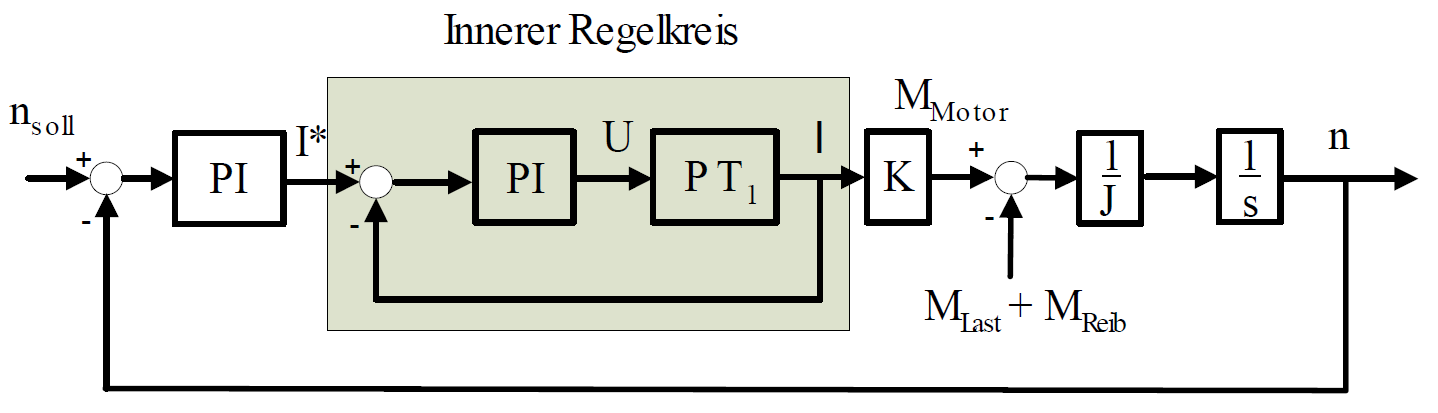
This experiment deals with a variable speed three-phase induction generator whose rotor winding is fed by a converter via slip rings. Depending on the converter design, the induction machine can efficiently be operated within a relatively vast speed range by feeding amplitude- and frequency-variant currents into the rotor circuit.
Using a DC machine as load, different characteristics are determined for engine braking as well as for regenerative braking, and the influence of the converter control on the motor performance is investigated.
The items analyzed and visualized in this experiment are e.g.
- operation as cage rotor for comparison,
- power flow on rotor and stator side at variable speed and converter supply,
- influence of rotor voltages and currents and their frequency on the power flow.
Series-wound DC motor fed by DC pulse-controlled converter (chopper)
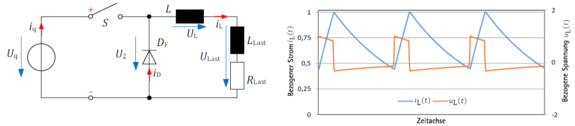
This experiment shall demonstrate the performance of a series-wound DC motor fed by a chopper. In contrast to an approximately ideal DC supply, the machine is supplied with a DC current that is clearly subject to harmonics.
The following measurements are made for different operating points:
- current ripple,
- mechanical and electrical power,
- motor efficiency.
The values measured are plotted as characteristics (e.g. speed-torque characteristics).
Permanentmagneterregte Synchronmaschine als Traktionsantrieb im Elektrofahrzeug (PMSM)
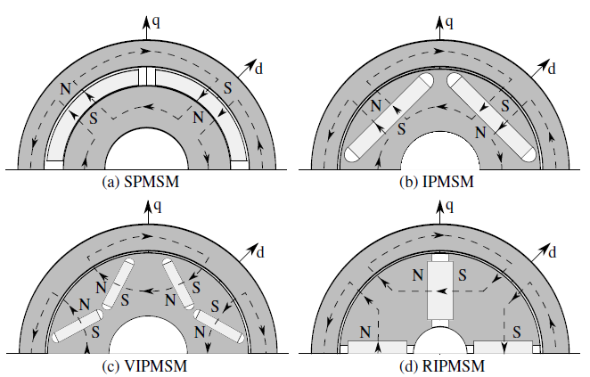
Ziel des Versuchs ist, den thematischen Bereich der Elektrotraktion mit besonderem Bezug auf die permanentmagneterregten Synchronmaschinen näher zu betrachten. Die zwei Schwerpunkte des Versuchs liegen dabei zum einen auf der Untersuchung der Eigenschaften und Besonderheiten der PMSM selbst und zum anderen auf der Anwendung der PMSM in einem modernen elektrischen Antriebsstrang.
Der Versuch betrachtet unter anderem:
- Messung von Maschinenparametern
- PMSM beim Umrichterbetrieb
- Wirkungsgradmessung
Permanent-magnet servo drive
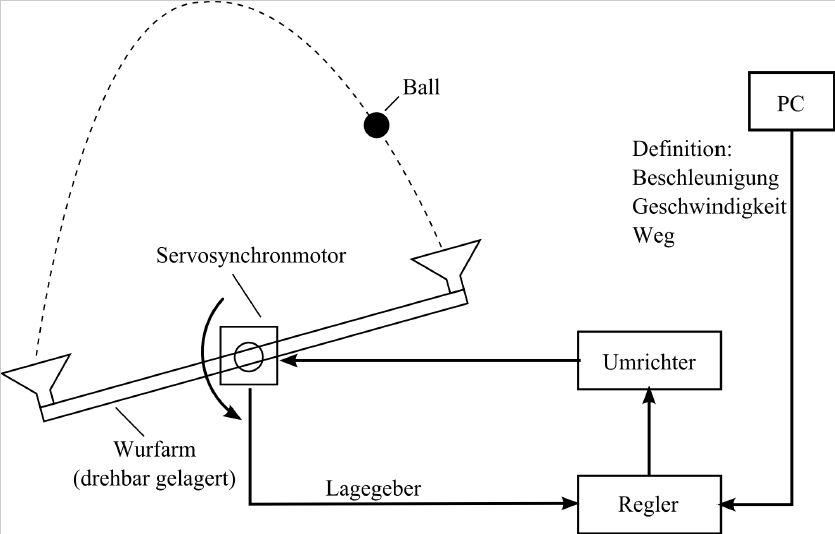
Topic of this laboratory exercise is to investigate the performance of speed- and position-controlled pemanent-magnet servo drives using the example of a throwing limb. By presetting acceleration, speed and distance profiles, small balls of different masses and properties are thrown and caught.
The influence on the control dynamics in dependence of the max. acceleration, traversing speed and deceleration as well as the influence of delays for compensating mechanical transient phenomena and inaccuracies when initializing the rotor sensor can be investigated by experiments.
The possibilities and limits of a servo-controlled drive are clearly shown by presetting different motion profiles and throwing heights.
Stepping motor
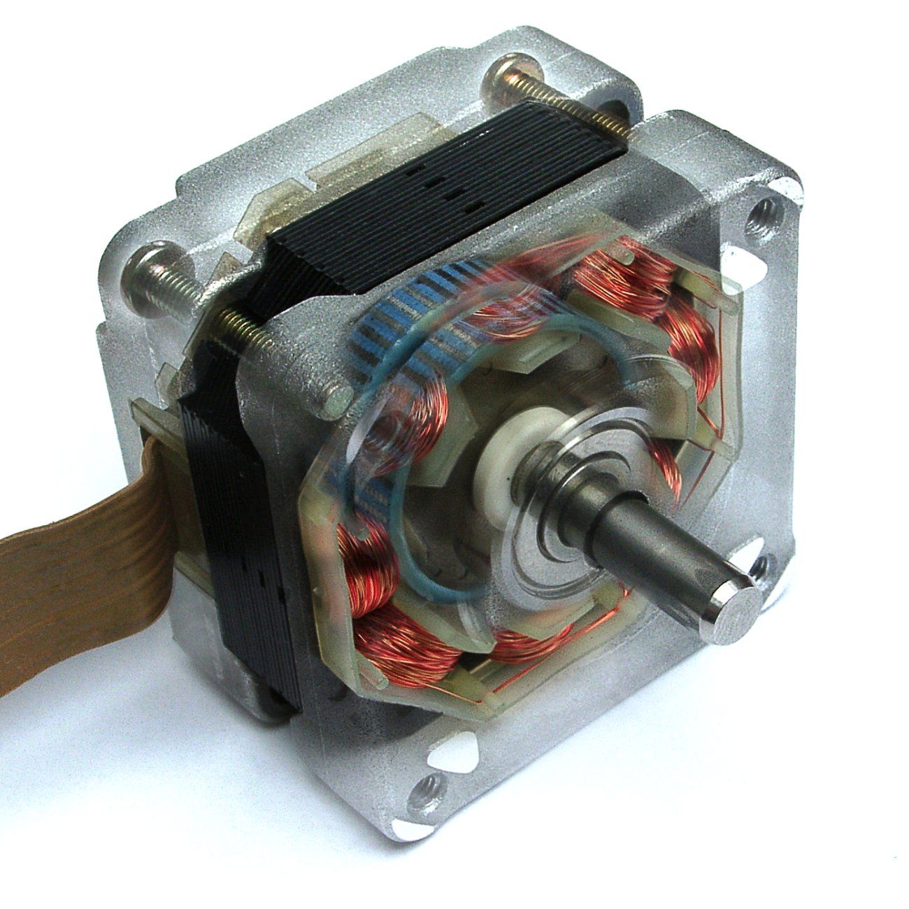
This experiment explains startup and function principle of a stepping motor. For this purpose, a control based on Matlab/Simulink must be developed to operate the motor. The rotor position is determined as a function of time by means of a resolver. The control shall also be suitable for half- and full-step operation.
The following items shall be explained and determined:
- transient response,
- critical frequency,
- detent torque and holding torque.